Current Sensor IC Accuracy Meets Smart Design
Understanding How Integrated Current Sensors Cancel External Disturbances
Maintaining excellent accuracy in challenging environments
Integrated Current Sensors (ICS) from LEM are engineered to deliver compact, cost-effective, and high performance current measurement across a wide range of applications. Beyond their electrical insulation and high surge resistance, one of their key strengths is their ability to maintain exceptional accuracy, even in challenging environments where external magnetic disturbances and temperature variations can affect the signal. Products such as the GO Series combine advanced packaging with a small differential Hall-effect sensing principle to meet the requirements of today’s automotive and industrial applications, where space, cost, and robustness are critical.
Differential Measurement Principle
Traditional Hall-effect current sensors rely on a magnetic core to concentrate the magnetic field and shield the sensor from external interferences. While effective, this approach introduces bulk, cost and thermal constants. LEM’s Current Sensor IC technology takes a smarter approach by eliminating the magnetic core entirely. Instead, two matched Hall-effect elements are symmetrically placed on opposite sides of the current-carrying conductor. Each sensor picks up both the target magnetic field (B) and any external stray field (Bext). These Hall cells are wired in a differential configuration.
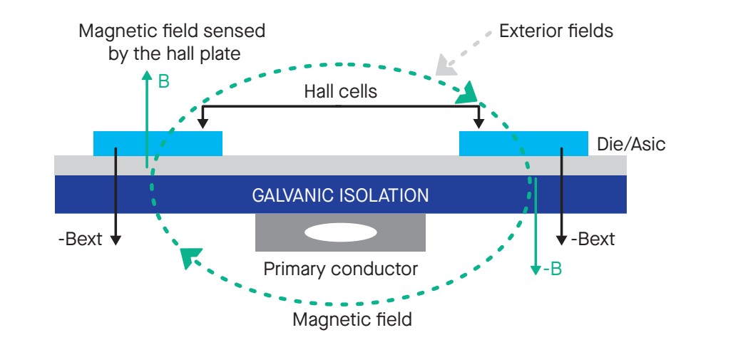
(B + Bext) ? (-B + Bext) = 2B
As a result, the external field is effectively cancelled, while the desired signal is amplified twofold. This innovative structure enables sensors IC to maintain accuracy and robustness in harsh environments without the need of a magnetic core. This configuration also ensures that no residual magnetic offset is introduced, as symmetrical placement and differential wiring inherently cancel static magnetic bias from the environment. Only electrical offsets, which are easier to calibrate, remain.
A Breakdown of Error Sources
Accuracy in current sensing isn’t defined by a single number; it is the result of many parameters including reference voltage deviation, offset, linearity, and sensitivity drift. LEM takes a systematic approach to quantify these factors, both at room temperature and across the full operating temperature range.

Errors at Room Temperature (+25 °C)
At room temperature, key contributors to total error include:
- Reference Voltage Error (?ref): Deviation of the internal voltage reference in ratiometric output
- Offset Error (?oe): Output value when no current is applied
- Sensitivity Error (?s): Variance between expected and real gain (mV/A)
- Linearity error (?l): Deviation from a perfect linear response
Each parameter is quantified and measured in absolute (mV or A) or relative (%) terms. To estimate the global error, LEM uses two models:
- Max Error: Sum of worst-case individual errors
- Root-Sum-of-Square (RSS): A more realistic estimate assuming independent errors
GO 10-SME Example
- Max Error: 87.4 mV (secondary) or 1.46%
- RSS Estimate: 63.5 mV or 1.06%

Thermal Drift Across Operating Range
Current sensor ICs must remain accurate across wide temperature ranges, typically -40°C to +105°C or higher. Temperature variations cause drifts in reference voltage, offset, and sensitivity.
- TCref: Variation of the reference voltage
- TCo: Thermal offset drift (mV/°C)
- TCS: Sensitivity drift in ppm/°C
Using the same RSS method, the total thermal drift can be estimated and combined with room temperature errors to provide a full error budget. While the sensor’s intrinsic thermal drift is minimized by design, many systems can implement software-based compensation utilizing known thermal behavior curves (TCo, TCs), especially in safety-critical applications.
GO 10-SME Example
- Max Error: 195.4 mV (3.25%)
- RSS Estimate: 100.75 mV (1.68%)
Current Sensor ICs Accuracy Drives Application Success
Applications such as EV powertrains, solar inverters, or industrial motor drives demand precise and consistent current feedback to ensure both performance and safety. Even small measurement errors can result in:
- Reduced power conversion efficiency
- Activation of protection features
- Compromised system performance
Repeatability is also important; a sensor’s ability to return to the same output for the same input across time, power cycles, and thermal excursions. Integrated Current Sensors designs from LEM are rigorously tested for hysteresis and long-term drift, ensuring consistent feedback during the entire life of the system.
ICS technology from LEM helps prevent these issues by offering:
- High repeatability through minimized external magnetic interference
- Stable performance across temperature variations
- A compact design removing the need for ferrite cores and extra shielding
Integrated Current Sensors – The Future of Current Sensing
LEM’s Current Sensor IC embody a smart design and achieve high-accuracy current sensing without the added bulk and cost of magnetic cores. They are designed to meet evolving standards in compact form factors while ensuring robustness, immunity to disturbance, and thermal stability. With continuous innovation in ratiometric output, signal conditioning, and packaging, integrated current sensor technology is positioned as a key enabler of smaller, smarter, and more reliable current sensing solutions.